There are a lot of monitoring solutions that can be accomplished with the DHT22 (temperature & humidity) sensor. The DHT sensors comes in two models and packings – the DHT11 and the DHT22. In addition, you might find the sensors in a small shield/board module or by itself, see pictures below.
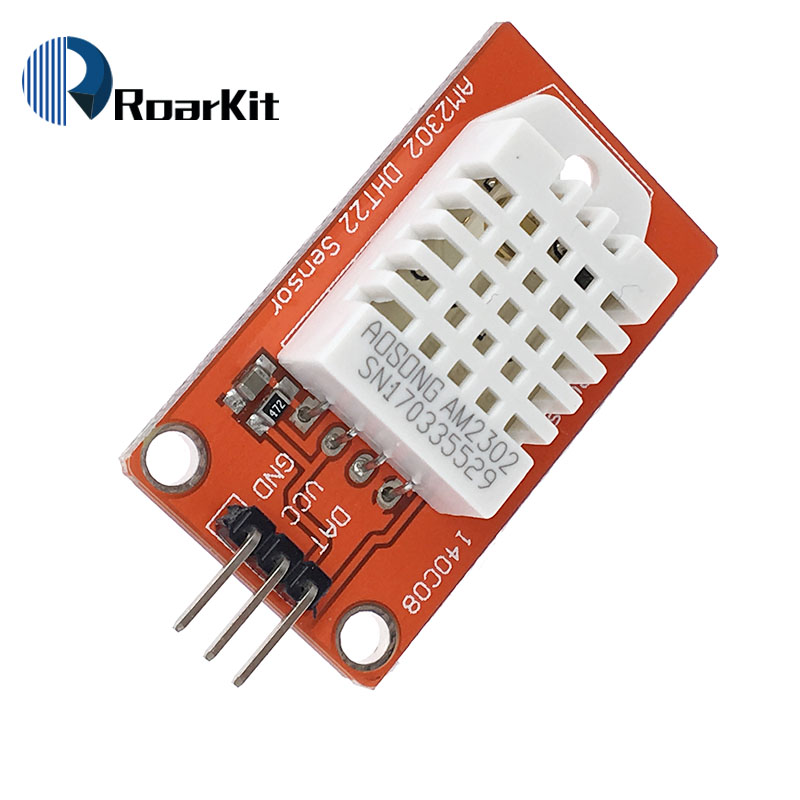
Fig 1: Tinker ready DHT22 Sensor 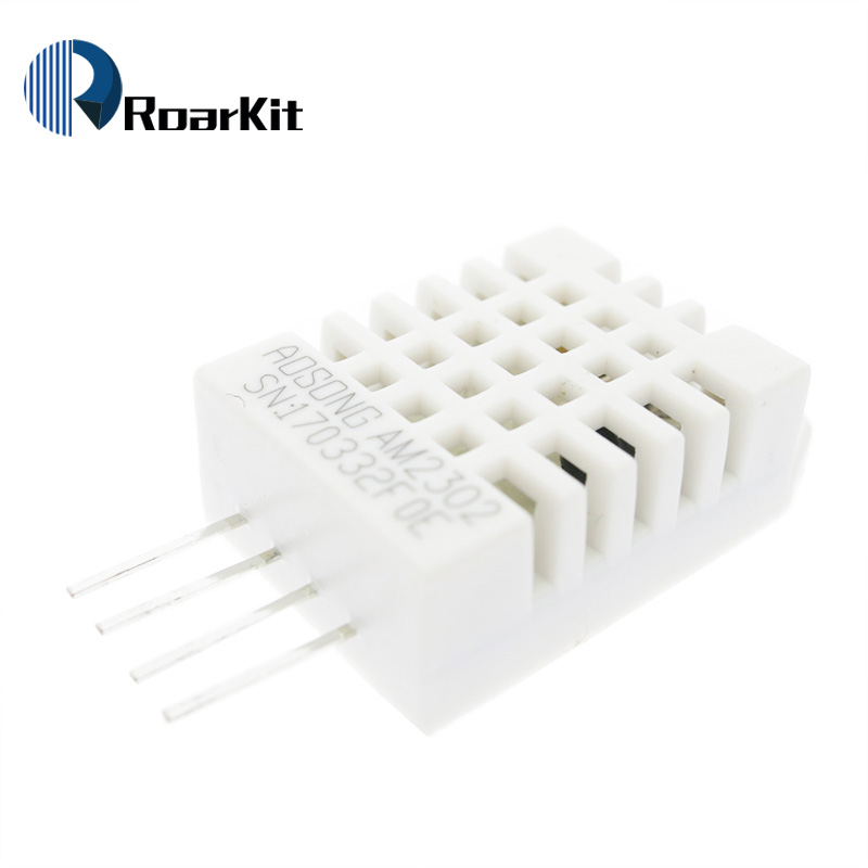
Fig 2: Standalone DHT22 Sensor
The main different between the standalone sensor and the others, is that you will need a 4.7k-10k pull-up resistor in your circuit when connecting the standalone DHT sensors.
DHT22 Technical Details
The DHT sensors uses one digital pin to communicate with the MCU. The DHT11 is more precise in terms of readings than the DHT22.
DHT22 Specs
- 3 to 5V power and I/O
- 2.5mA max current use during conversion (while requesting data)
- Humidity readings with 2-5% accuracy
- Temperature range between -40 to 80°C with ±0.5°C accuracy
- Only 0.5 Hz sampling rate so once every 2 seconds
Getting Started
If you haven’t install the Arduino IDE or setup your NodeMCU, then head to our Getting Started guide.
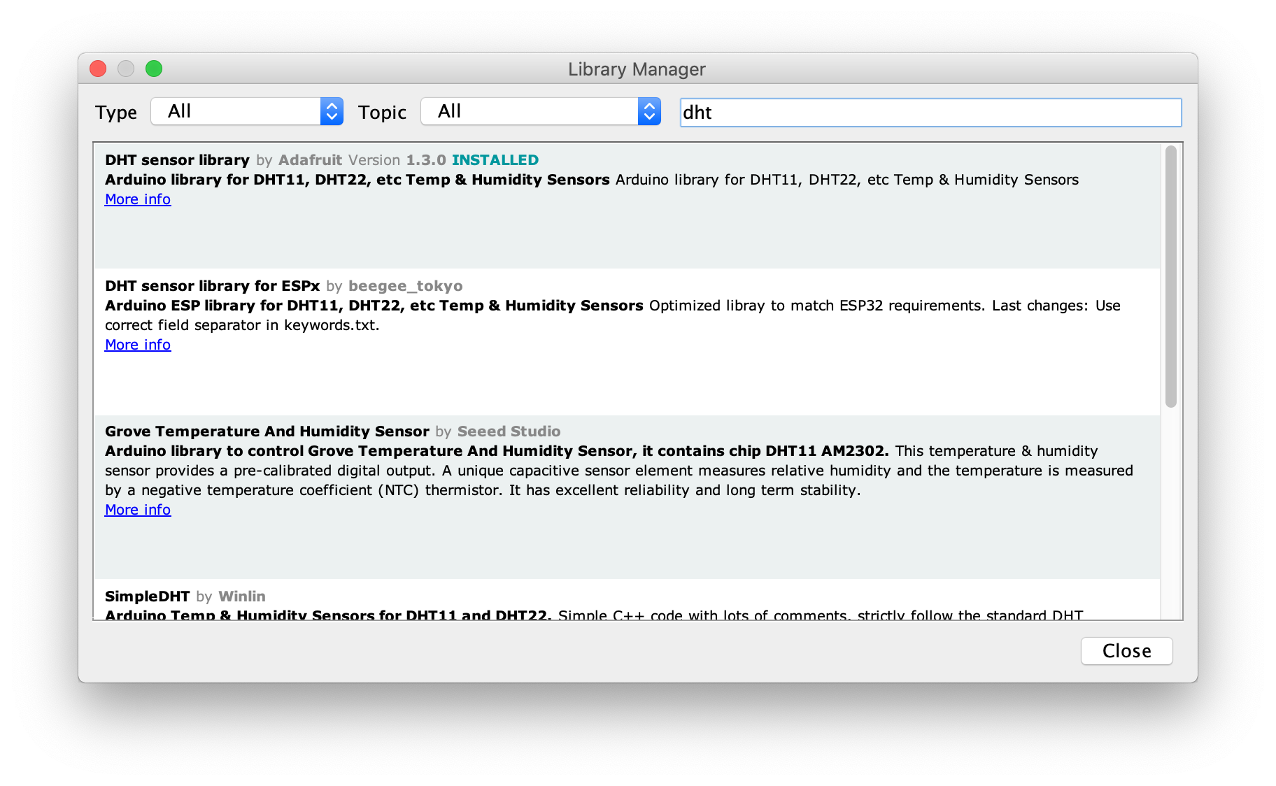
We’ll be using the Arduino IDE for this guide, hence open it and create a new sketch. Lucky for us, there is already a DHT library available so go to: Sketch > Include Library > Manage Libraries
Now search for DHT and installed the DHT sensor library by Adafruit.
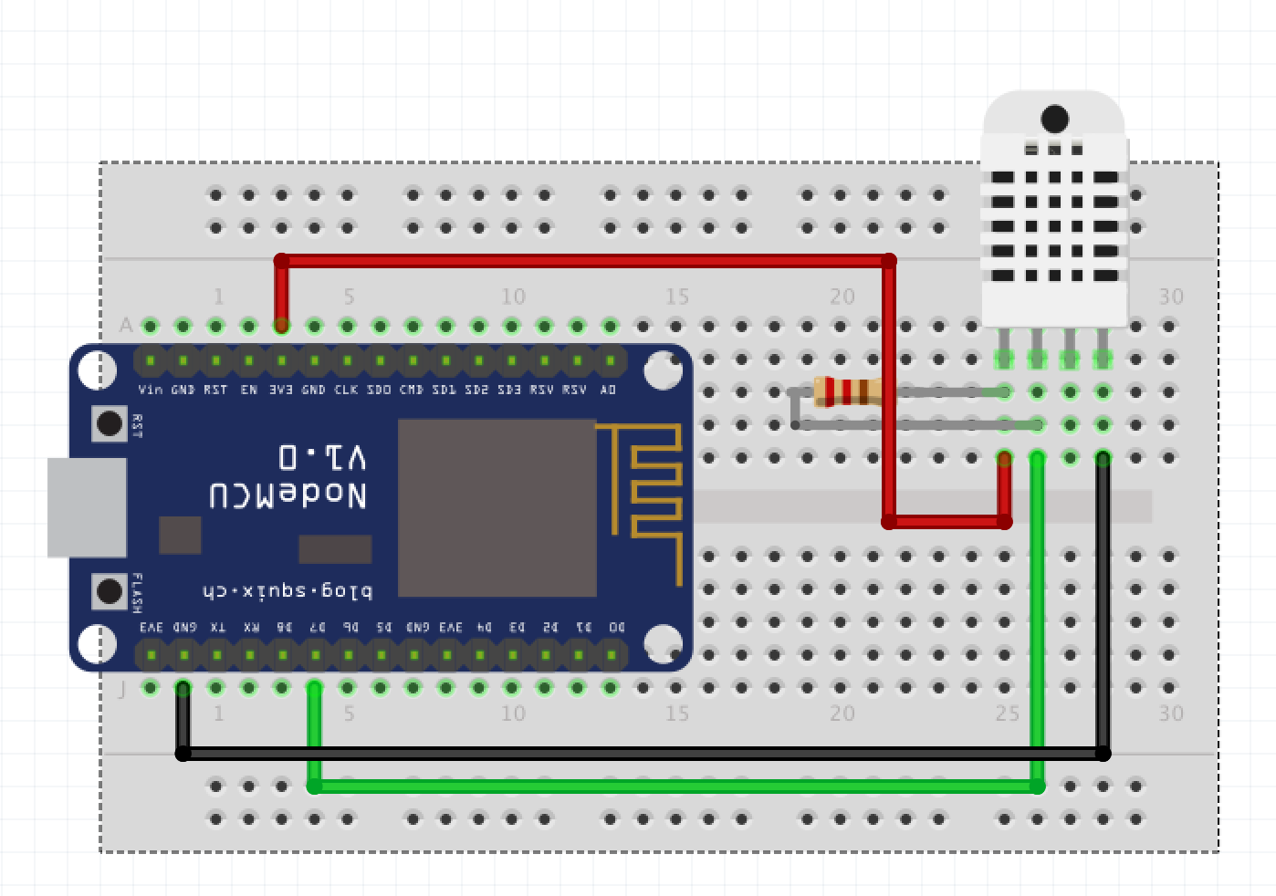
Let’s take a look at our circuit.
Code
There are a few different DHT libraries that can decode the temperature and humidity readings from the digital read out pin. For the purpose of this tutorial let’s use the Adafruit DHT Sensor Library

#include <dht.h>

dht DHT;

#define DHT11_PIN 7

void setup(){
}

void loop()
{
  int chk = DHT.read11(DHT11_PIN);
  delay(1000);
}